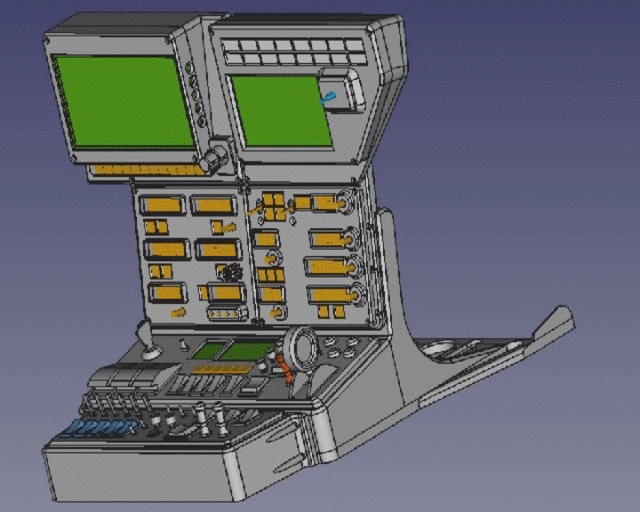
Another new and old project is building a “cockpit” for a flight simulator, not really a cockpit with seats and coffee maker, just an instrument panel with some switches. In the past i already built some panels, but they were just some switches in shoebox with some light bulbs. Many years ago as a kid i started my virtual pilot career with the flight simulator 1 and since then i was flying with all new appearing versions. Not only those from Microsoft, also X-Plane and many others. Last year, after 14 long years, Microsoft published a long awaited new version. Now, with my new 3D printer i’m able to print big parts (40cmx40cmx40cm), time for a new desktop “cockpit”.
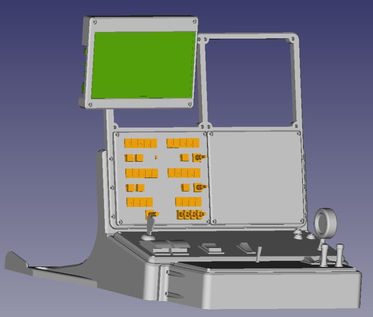
When i started the project i wanted to use 5″ TFT displays for the attitude and the system/weather/GPS-map display, they would have fitted perfectly in the top two panels. But unfortunately it turned out that their resolution is to low to read all the tiny numbers and characters, so i had to change to 7″ TFT displays … and of course they are to big for the already drawn console and of course too big for the printer. But maybe the overhanging panels will look pretty good at the end.
The electronics and programming are still pending, i first want to see how many switches and displays will fit into the available panels. I don’t want to build it bigger, it should stay a desktop console, easy to remove after my regular bad landings 😀
Update#1 / 210220 / CAD design and first panel printed
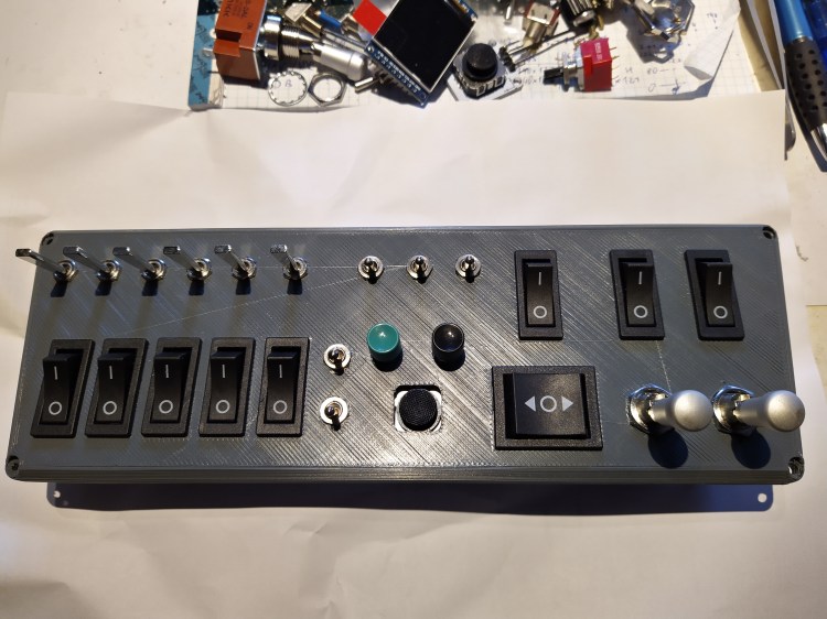
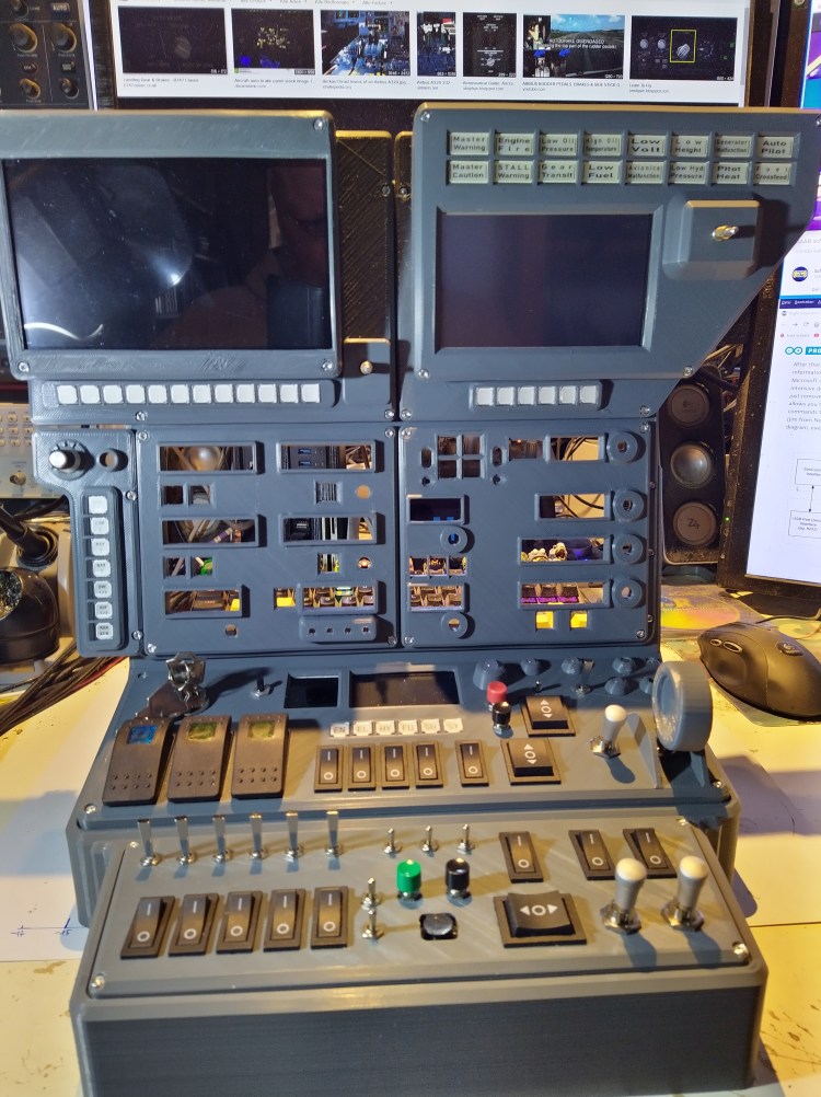
After deciding which switches and controls should be available for the pilot i continued designing the desktop cockpit. Some of them like a master power switch were easy decisions, others like bleed air switching or swim rudder retract/extension were not so easy because they are not existing in every type of airplane … turbine or piston, single or multi motor, seaplane or not seaplane. Since i want to use it for every type i skipped the bleed air switches but added a switch to extend and retract the swim rudder xD 😉
The first panel is printed and i assembled all switches. Of course as usual in a “prototype” something is wrong or fails or explodes … i totally forgot that there should also be a labeling and space for lables, i don’t want to accidentally dump my fuel somewhere in the middle of an ocean when i want to switch on the seat heating. Well, i think somehow i will be able to label the switches, maybe it will not look fancy then.
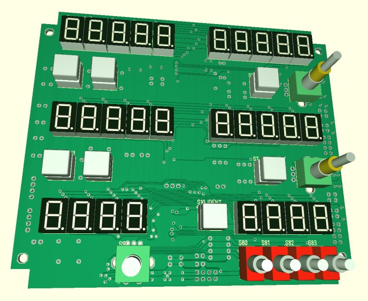
Update#2 / 210221 / Radio panel PCB
Some mind bending hours passed now, now the PCB for the radio panel is almost done. Laying some of the tracks seemed to be as walking in a maze without exit. But finally after rerouting some formerly layed tracks every signal found it’s place. Most of the parts are THT parts because i don’t like to solder those tiny SMDs. Just the 3 display controlers (MAX7219) and the port expander (MCP23017) are SMDs … but i’m thinking now to use more SMDs in the next design, that would at least make the PCB design process a little bit easier.
Update#3 / 210303 / Autopilot PCB and CAD preview
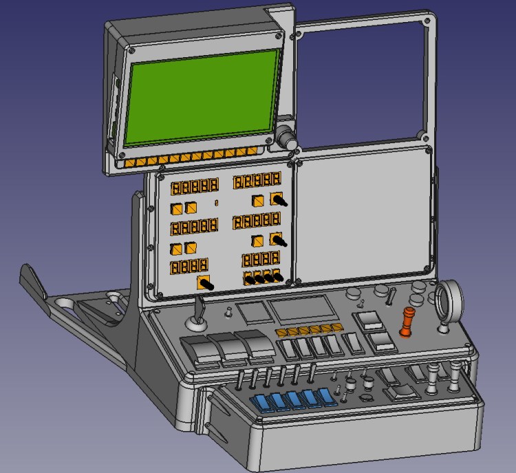
Some days are gone, another PCB design is done. The printer was busy too, after 64hrs of printing it spit out the main frame for the desktop cockpit, a picture will follow in a later update. Most of the panel/module are desigend and ready for the 3D printer, but have to wait a little bit to be printed, had to order new filament. Next bigger step will be the design of a master PCB which will connect to the simulator interface and the to all the switches and displays. Because i have a bunch of MCP23017s with DIL and SOIC packages i’m using them for all the digital DIOs, but because their number is limited to 8 devices on a I2C bus i will have to use a secondary I2C bus on my controller or maybe i have to add a secondary uC. I’m still not sure about that, but what i already know for sure is that i will use a Teensy3.5 as “main” controller.
Update#4 / 210317 / All panels printed and radio panel assembled
2kg dark grey PLA filament is gone and transformed into the desktop cockpit. I wasn’t sure about the finishing of the panels, should i apply a primer coating and some paint to them, or not ? … The decision was easy at the end, i keep the motto … rusty, dusty, dirty and unfinished 😀 …
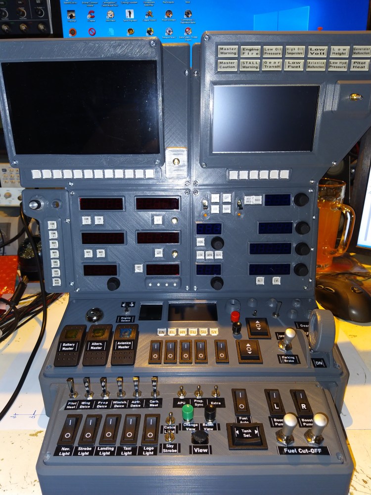
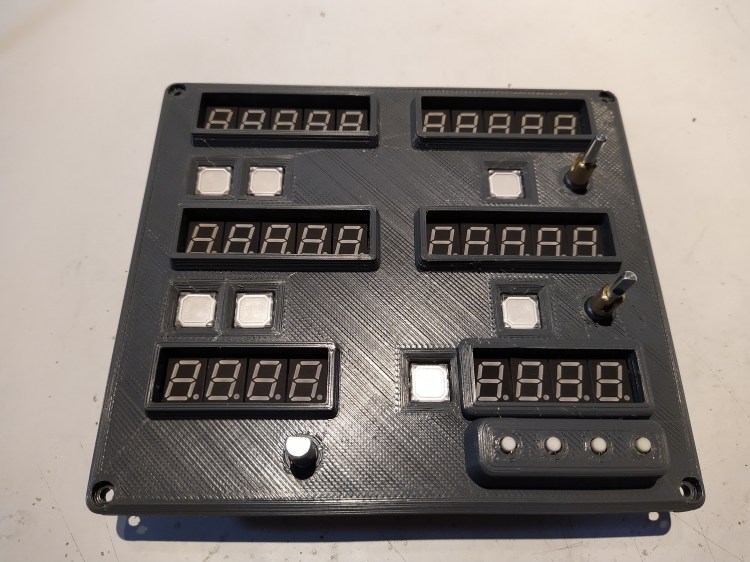
The radio PCB arrived some days ago, all electronic parts are assembled and soldered and it fits perfectly into the panel. I had again some concerns about soldering the 4 SMD chips (LED driver, port expander) with the 1.27mm pin pitch, but by using some new solder paste and a tiny solder tip it was quite easy (High five to the solder stop mask 🙂 ). Fortunately i found some red filter acrylic plates i had as left over from an earlier project, the displays are looking much better this way.
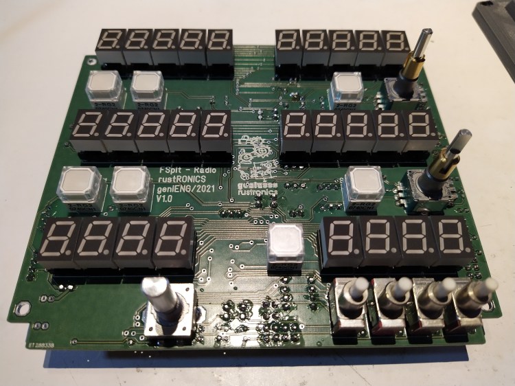

The first digit of the COM and NAV frequency displays is hard wired and a bit brighter than the other digits controlled by the display driver. Not sure why that happened, they should have the same brightness. Maybe the i did something wrong when calculating the resistor value for the current setting of the display driver … but no big deal to change them.
In the upper part of the last picture you can see the full color TFT and monochrome OLED display which i will use to display engine/electric/hydraulic/and more parameters. Actually the OLED shows spoiler and flaps deflection.
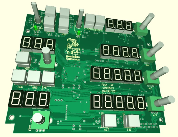
Update#5 / 210322 / Autopilot panel
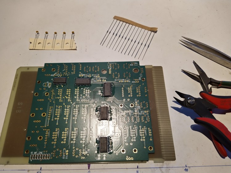
This was a run … the courier brought the blank PCB on friday evening, 24 hrs later it was already assembled and soldered. Had to print again the front panel, i forgot the cutouts for the rotary encoders on the backside. Now everything fits as expected, and again i won’t do any finishing to the ugly surface of the front panel … not rusty, not dusty, unfinished xD !


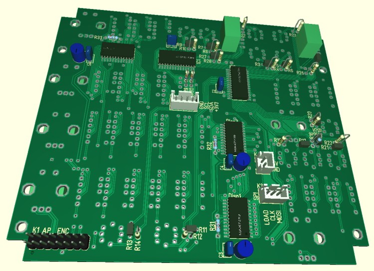
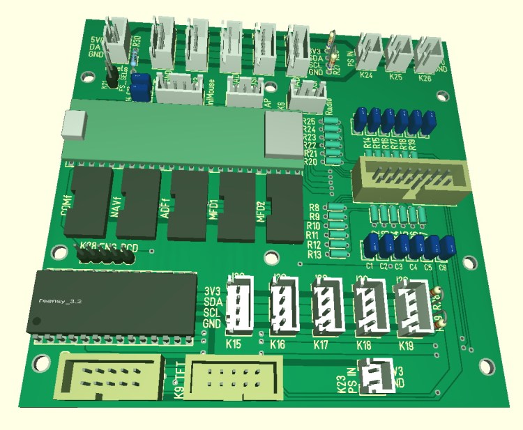
Update#6 / 230322 / Mainboard design and all parts assembled
The Teensy3.5 offers a lot of IOs, but even using 8 port expanders (MCP23017 ; 8*16IOs = 122IOs) isn’t enough. So i will use a secondary microcontroller, a Teensy3.2 because it was just there. When starting this project my plan was to build the master PCB on a simple experimental PCB, but now i’m too lazy, not motivated to make dozens of air wires and not in the mood for the troubleshooting afterwards … so i decided to make a dedicated motherboard. Routing is done, here is the PCB previes out of the CAD :
Finally all switches, front panels, indicators and displays are assembled to the mainframe. Now a lot of wiring and soldering and writing code is required, that will take it’s time, but i’m very eager to use it asap … it will be definitely not be a dust and rust collector 🙂